Brakes and coupling
Prodigy Brake Controller (Guide Only)
Initial Set Up
‘C’ should be showing on display. This means you have complete circuit connection to brakes. Press button on top right hand side to bring up display ‘b1’ (boost level 1). Press again to show ‘b2’ and once more for ‘b3’. Press again to come back to ‘C’. Set the trailer on ‘C’ or ‘b2’ when fully loaded.
Pull the manual lever across to the left and hold. Adjust left hand top wheel until display reads 6.0. You are now ready to drive away. Release the lever. These settings may vary for each controller.
Road Setting Brakes
Drive tow vehicle and trailer on a dry level paved surface at 25 kilometres per hour and fully apply the vehicle brakes. If the trailer feels to be pushing the vehicle, then increase the reading on the display by rotating the left hand wheel to the front (P2 and P3 controllers have up and down adjusting buttons). Set the display at 7.0 and try again. If the trailer is pulling up the vehicle quicker than would be experienced without the trailer attached, reduce the setting on the display to 5.0. Continue to test until the trailer is not influencing the braking of the tow vehicle.
REDARC Tow Pro Elite Brake Controller
Operating Modes – The Tow Pro Elite has two modes
Automatic (Blue LED) and
User controlled (Green LED).
When operating in automatic mode the Tow Pro will apply the trailer brakes at a level proportional to the vehicle deceleration. This mode is designed for highway traveling or everyday use.
The braking level can be adjusted using the gain control knob on the remote. Use level 5 as a starting point. Should lighter braking be required, turn the gain control knob to <5 to reduce the trailer braking force relative to the vehicle braking level. Turning the knob to >5 will increase trailer braking force. The LED will turn RED when brakes are applied. The higher the braking force, the brighter the red LED will glow.
In ‘user controlled’ mode, the Tow Pro will apply the brakes to the level you set. The gain control knob has level 0 – 10, with 0 being that trailer brakes have zero braking and 10 being full trailer brake application. This mode is for off road use. It is recommended you start below level 5 and adjust the gain control knob once braking requirements are established. The LED will turn RED when brakes are applied. The higher the braking force, the brighter the red LED will glow.
Wearing In The Brakes
As the trailer is new the brakes need to wear in, which will make them more effective. As this occurs, the brake controller will need to be reset to bring braking back to a less aggressive response.
When the trailer is fully loaded with water and gear there can be a weight increase of up to 500kg. The brakes will need to be adjusted at the controller to increase the braking to compensate.
Always adjust the controller to try to achieve a neutral braking result for the tow vehicle, i.e. the trailer is neither pushing nor pulling the tow vehicle while stopping.
Other Reasons to Adjust The Controller
When travelling at high speed on dirt or tar roads we recommend increasing the brake controller setting to allow maximum braking in an emergency. Bring the setting back to normal in town traffic.
Turn the brake controller down or off when driving on soft sand as sudden braking can bog the vehicle and trailer. Hard sand driving can be done with a normal setting. Adjust the brake controller when 4WDing to suit conditions.
When travelling down a long steep incline, select a lower gear and use the brake intermittently to reduce as much speed as possible. Do not ride the brakes as this will overheat the brake components and reduce the stopping power of the brakes.
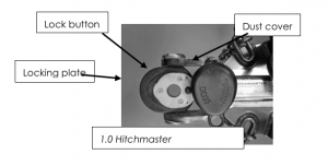
Hitchmaster DO35
Your DO35 Hitchmaster coupling has a 3500kg towing capacity and can be used with load distribution hitches, providing the coupling movement is not obstructed and the maximum downward load of 350kg is not exceeded.
Coupling Instructions
- The trailer should only be coupled on level ground; the trailer hand brake must be on
- Make sure the vehicle’s towing pin and the trailer’s coupling are free of sand, dirt and foreign objects, and are lightly lubricated
- Raise height of the trailer coupling above the tow vehicle’s towing pin by adjusting jockey wheel
- Connect the trailer safety chains to the tow vehicle using load rated shackles; the chains should cross over each other – left chain connects to the right side of the tow bar and vice versa for the right chain
- Push and hold lock button down, push locking plate to open position until lock button springs back
- Align coupling over towing pin by moving either the vehicle or the trailer and lower
- Ensure that coupling is fully seated on the towing pin
- Push the lock button to release the plate forwards into the locked position
- Assemble the dust cover by snapping in the back edge of the seal first then pushing down on the front. Dust cover can only be installed if the lock plate is in the locked position and will emit an audible snap when assembled correctly
- Retract and stow jockey wheel, remove and store jockey wheel handle, release trailer hand brake, connect the trailer wiring harness, breakaway brake safety lead and Anderson plug to the tow vehicle before commencing towing
Uncoupling
- The trailer should only be uncoupled on level ground
- Chock wheels and apply trailer handbrake
- Remove dust cover
- Push and hold lock button down, push lock plate to open position until lock button springs back
- Raise height of the trailer above vehicle towing pin by adjusting jockey wheel
- Disconnect safety chains, wiring harness, breakaway brake safety lead and Anderson plug before moving tow vehicle
Maintenance and Safety
- Keep hands and fingers clear of coupling when attaching
- Ensure trailer safety chains are attached whilst coupling or uncoupling
- Keep towing pin and coupling mating surfaces clean and lightly greased at all times
- Regularly lubricate grease point with multi-purpose grease
- Check all bolts regularly for tightness
- Do not use towing pin or coupling for recovery purposes
- Periodic adjustment of slotted nut and pin may be required and should be performed by a qualified repairer
- Flush with water if locking mechanism does not open fully due to dirt ingress
Power
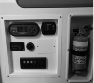
12 volt Main Isolating Switch
The isolating switch is located on the control panel inside the entry door, except for in the Aurora where it is on the panel above the fridge.
This MUST be turned to the off position when travelling. This isolates the entire 12-volt system from the batteries but will not affect the charging of the battery or operation of the fridge while travelling or solar input whilst stationary camping.
This MUST be done each time you leave the trailer for any period of time. The inverter, fridge and water pump all have individual isolation switches but only the pump and lights are controlled by the main switch.
12 volt Internal and External Sockets
The 12 volt sockets can be used to power 12 volt appliances of low current draw such as lights, fan, phone, laptop charger etc.
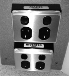
240v Power Outlet System
The trailer is fitted with two internal and one external mains 240V AC power outlets, and two internal and one external 240V inverter power outlets. Power from 240v mains is available when trailer is plugged into a supply at your home or powered site.
NOTE: The position of power outlets vary model to model. Each power outlet is labelled to identify the power output type.
Inverter
Your inverter must be turned on before you can use the inverter outlets as described above.
Your inverter is not recommended for use with appliances that produce heat as this may cause it to overload.
NOTE: Turn inverter off when not in use as it will continue to draw power.
The inverter power outlets become activated once the inverter is turned ON. The inverter control switch is located on the control panel.
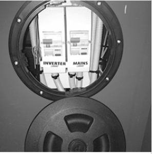
Both types of power outlets are protected by a residual current device (RCD) safety circuit breaker. An RCD is a life-saving device designed to prevent you from getting a fatal electric shock if you touch something live, such as a bare wire. It can also provide some protection against electrical fires. The RCD labelled ‘Mains’ and ‘Inverter’ are located in the seat module and must be in the switched ON, for the power points to be activated (refer picture 2.2).
All power outlets are activated when you see the (I) and the switch tab is in the up position. The power points are isolated or off when the switch tab is in the down position and you see the (O). This can happen when the RCD has been tripped. Refer to Electrical System: Trouble Shooting.
NOTE: Vibration while travelling may trip RCD’s. Please check RCD before using power points or plugging trailer into Mains power for charging.
NOTE: If items usage watts is greater than the size of the inverter it will over load and the item will not run. If the usage watts do not exceed the inverter size, then you may use the appliance. Some items have a greater usage at start up.
If you are charging mobile phones and laptops we recommend you charge during the day when excess solar capacity is usually available. Always keep an eye on your REDARC display to monitor the usage and the State of Charge (SOC) of your trailer batteries. Refer to Electrical System – Control Panel and Switch Panel layout for location of REDARC Display and refer to REDARC Display: Understanding menu screens, for more information on battery monitoring. If inverter does not power up, check the mega fuse.
Water
Hot Water System (HWS)
To ignite the heater, turn on the gas at the gas bottle – ½ to 1 turn will be sufficient. Open the outside HWS air vent (right hand side of trailer) by undoing the metal dust cover and removing the inner plastic cover (which can be stored on the Velcro tabs inside the metal dust cover). Press the HWS ignition switch located on one of the dinette seat faces to the desired temperature (up for 60 degrees or down for 70 deg.); water will be hot in about 15 minutes.
The heater can be left on and will continue to keep the water hot however, it is advisable to switch off the heater and gas at the bottle before going to bed, or when leaving the trailer unattended. The water in the heater cylinder will usually remain warm for several hours. The gas and hot water system MUST be turned off and air vent covers MUST be secured before travelling.
Filling The Water Tanks
- Insert the key, unlock the filler cap and turn it anti-clockwise to open and remove the cap.
- Insert water hose (remove any hose fittings) into filler and push it down inside the filler neck tube.
- The water tank will not fill easily if the hose is not inserted into the filler tube; try using a torch to assist in locating the filler neck.
- Turn the tap on part way. If you try and fill the tank too quickly the air cannot escape. Water will back up in the filler neck and bubble out; leading you to believe the tank is full which may not be the case.
Water Tanks
It is recommended you drain your water tanks if the trailer is not going to be used for a period of time.
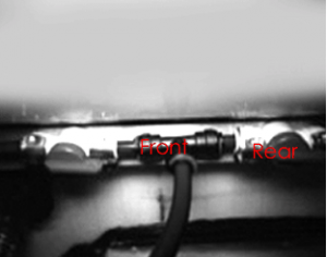
To drain the back tank, locate the tap under the trailer on right hand side at rear of the tank. To drain the front tank, locate tap under the trailer on right hand side just in front of the wheel.
To drain the optional 60L tank (mounted over the axle), open the valve on the back of the tank.
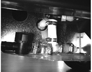
River Access System (RAS)
To use your RAS access, you MUST be using your front water tank (tank selector valves are located inside the trailer, under the dinette).
Under your trailer just in front of the right hand wheel you will find 3 taps
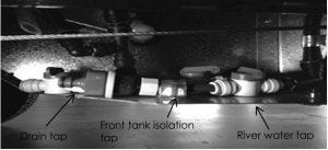
The rear blue tap should be in the OFF position unless draining the front tank. The front tank isolation tap should be turned to the OFF position. The river water tap should be turned to the ON position.
You can now attach a hose to the grey hose connection and draw water into the trailer from a bucket or other water container placed beside the trailer.
To turn off the RAS reverse the above procedure.
NOTE: While this system is referred to as the River Access System, it is not recommended to pump directly from a natural water source as possible low water pressures in the suction line could damage the pump.
NOTE: Do not have both tanks switched on at the same time (refer picture 3.2). If the RAS is to be used, only select ¬the front tank.
DO NOT connect the RAS to the town water supply, as it will damage the water system. The piping, fittings and pumping system are low pressure and not designed for town water supply pressure. The RAS allows use of water from an outside source. It cannot fill the water tanks fitted to the trailer; these can only be filled via the water fillers. The pump and plumbing system will work as normal however, the water will be drawn from the outside source.
Water Filter
To remove the cartridges, shut off water supply. Place some towels around base of filters and over all electrical equipment. Using the white spanner provided, unscrew the filter case.
- Twist cylinder case to left until it is released
- Pull cartridge down and out of head
- To install new cartridge, align bump on cartridge with label
- Insert cartridge
- Grasp head firmly and twist cartridge to right until it stops
- Replace cartridge case
- Turn water supply back on and check there are no leaks
Replacement cartridges are available through our online shop www.australianoffroad.com.au/shop caravan and camping stores and some major hardware chains.
Toilet and Black Water Tank System
Operating The Toilet
- The toilet has power and water at all times.
- Use biodegradable toilet paper at all times. Failure to do so may block the toilet and is not covered by warranty.
- When cleaning only use biodegradable products recommended for toilets. Do not use vinegar or Bi-carb as they can dry out the pump seals.
- The toilet is only flushed with water from the rear water tank.
- To flush the toilet, push the small black button located near the toilet. This is a variable flush toilet and will flush as much or as little water as required, depending on how long the button is held down for.
- The black water tank gauge is mounted in the control panel inside the door. (Note: Aurora control panel is above fridge)
- If the electronic gauge has malfunctioned for any reason, there is a black tank visual gauge (clear plastic tube) located on the outside of the front right section of the drawbar. This tube will show a constant indication of the fluid level in the black tank.
- The black water tank is vented through a charcoal filter located on the front right corner of the front storage area behind the stone guard. There is a panel in front of this filter and a hose fitting on top of the filter. The hose fitting is to be used to back flush the filter breather tube back into the black tank should the breather become blocked.
NOTE: When the tank gauge shows the black water tank is three quarters full, the black water tank may soon need emptying. If the trailer has not been on a level surface, the gauge may not provide accurate readings. Movement of persons in the trailer when reading the tank gauge may also affect the accuracy of the reading.
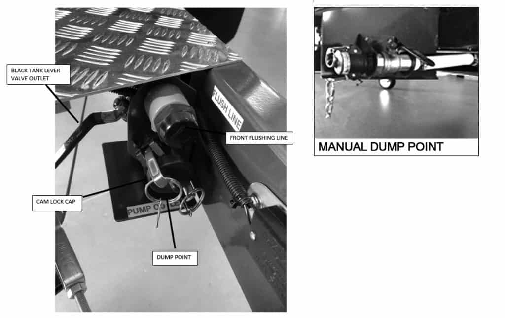
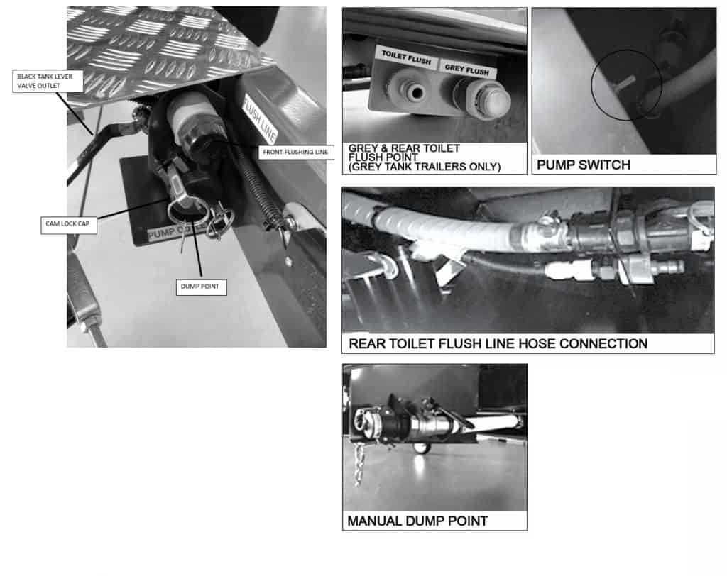
To Manually Dump Black Water Tank
- To manually dump your black water tank, remove camlock cap and connect your dump hose to the manual outlet and the other end into a portable tank or dump point
- Open lever valve for manual outlet. As it is gravity drained, it is desirable to park your trailer so the right side is a little higher than the left side
- Attach a garden hose to flushing line at the front of the trailer and turn water on until water runs clear
- You may need to do a couple of trips to empty your portable tank depending on its size
- Once empty close manual outlet valve, disconnect garden hose, disconnect dump hose and refit camlock cap.
TIP: Coil your dump hose and connect its ends together; this will seal the hose and helps avoid leaks or odours. NOTE: To flush clean the black water tank, a garden hose with town pressure is required.
Black Water Tank Dumping Via Pump
- Go to any dumping station. For a comprehensive list on where these are, please refer to Wikicamps Australia
- Attach dump hose to the waste pump outlet located on the front left side of the trailer and the other end to dump station
- Open black lever valve located above camlock fitting where the dump hose connects to drain contents of tank
- Turn on pump switch located inside the front storage locker (awning side)
- Whilst tank is draining, attach a garden hose to the outlet labelled ‘flush point’ and turn water on
- Continue until flow from dump hose runs clear, then turn water off and disconnect garden hose
- Pump until tank is empty then turn pump switch off. Do not run the pump dry as it will damage the impellor
- Turn black lever valve off and remove dump hose – roll up and join ends to prevent leakage or odours
- Fit reverse flush fitting to pump out point, attach garden hose and turn water on for 15 seconds
- Disconnect the garden hose, clock black lever valve, remove flush fitting and refit camock cap
Black Water Tank Dumping When Storing Your Van
- Complete steps 1 to 6 as above
- Connect garden hose to rear flush point located rear of the driver’s side wheel. Turn water and blue inline valve on and flush for 2 minutes
- Turn water and blue inline valve off and remove garden hose
- Complete steps 7 to 9 as above.
Dumping Grey Water Tank
- Go to any dumping station. Refer to Wikicamps Australia for a comprehensive list of locations
- Remove camlock cap and attach dump hose to grey tank outlet located right hand side of trailer next to rear tank drain and the other end to dump station
- Open black lever valve to drain contents of tank
- Whilst tank is draining, attach a garden hose to the clearly marked ‘grey flush point’ and turn water on
- Flush tank until discharge flows clean, then turn off and remove garden hose.
- Leave draining until empty then close black lever valve, remove dump hose and refit camlock cap.
NOTE: The emptying process can take a few minutes.
TIP: Coil your dump hose and reconnect its ends together; this will seal the hose and helps avoid leaks or odours.
External 82L Evakool Fridge/Freezer (Quantum & Quantum Plus)
To adjust the temperature, press down the “SET” button (in the middle of the controller) the current temperature will be displayed.
- Use the upper and lower buttons to adjust temperature up or down as required – Evakool recommends -16*C.
- The fridge temperature range is -20*C to +10*C
- Press “SET” again to lock in the required temperature
- The symbol * will appear on the top left hand side of the display when the compressor is running
and cooling - The on/off switch is located at the back of the fridge on the top right hand side
Internal 130L Vitrifrego fridge/freezer (Matrix & Matrix Pop top)
Internal 146L or 175L Evakool fridge/freezer (Aurora)
Internal 75L Vitrifrigo fridge/freezer (Odyssey)
- Refer to the handbook supplied for instructions